
QC Notes Level-24
ROTATING EQUIPMENT ALIGNMENT PROCEDURE, STANDARDS
✅ INTRODUCTION
Aligning rotating equipment requires a few steps. Begin by disconnecting the power supply, locking out and tagging the equipment, removing the coupling guard, and loosening the coupling bolts. Additionally, inspect the condition of the bearings, seals, and couplings, replacing any worn or damaged parts.
Accurate alignment results from successful execution of three key steps: (1) Calibration, (2) Train Time, and (3) Run Time. Calibration and Train Time tasks are only executed during setup, while the run time tasks are executed during production operation.
There are four main types of alignment commonly used in design: left alignment, right alignment, center alignment, and justified alignment. Left alignment aligns text or objects along the left margin, creating a clean and structured look.
Alignment involves the evaluation of every geometric orientation with various components and systems being in two-dimensional data points which relate to the positioning of the components. These techniques are often one of the best answers for the component position in which they evaluate the straight lines and planes.
✅ ALIGNMENT PROCEDURE
- Indicate and Record Rim (Radial) Reading @ 6:00 Oclock
- Indicate and Record Face (Angular) Reading @ 6:00 Oclock
- Use Formula to compute the shim
+ sign means shaft is low so add shim
-sign means shaft is high so remove shim
Formula:
S1 = ±R/-2 + ±F × B / A ➢ S1 = B/A × F + R/2
S2 = ±R/-2 + ±F × C / A ➢ S2 = C/A × F + R/2
- Where:
o S1 = shim needed under Front fooS2 = shim needed under Rear foot
o R = rim reading at the bottom
o F = face reading at the bottom
4. Install or Remove Shim as required
5. Repeat 1 & 2 as needed. If reading is within tolerance the alignment is satisfactory
✅ CLEANING (SEAS-L-350):
- During project proposal and detailed design, detailed procedures for cleaning and flushing of the piping spool and systems shall be established identifying acceptable methods.
- All pipes shall be internally cleaned by air blowing prior to installation.
- Pressure Testing of the piping systems shall be in accordance with SAES-A-004 and SAES-L-150.
- Lay Up Requirements after cleaning and pressure testing has been completed shall be in accordance with SAES-A-007.
- All piping systems shall be flushed using high pressure (60.8mPa/8.8ksi) jet such as rotating hose or rotating nozzle.
- Below 4” use High Velocity Water Flushing (HVWF) with a minimum of 3m/s velocity. Flushing medium shall be plant/process water or raw water.
- When flushing stainless steel lines, the chloride ion content shall be less than 50mg/l. After flushing it should be completely drain, dried to a dew point below 1°C and protect against corrosion.
- Pneumatic Flushing with dry air (dew point – 1°C or less) or steam with a minimum exit velocity of 15m/s.
- Pressurized Air Shock Blowing (PASB) for initial cleaning for instrument air, plant air and as an alternative method cleaning method for initial cleaning of small bore pipe (less than 2 inch), working pressure shall never be more than 810 kPa (115 psi).
- Alignment of flange joints with spectacle plate is within the following tolerances:
- a. Vertical bolt hole offset ± (2.4mm + 30%) = ± 3.12mm.
- b. Horizontal bolt hole offset ± (2.4mm + 30%) = ± 3.12mm.
- c. Rotational offset ± (2.4mm + 30%) = ± 3.12mm.
- d. Combination of vertical, horizontal and rotational offset ± 3.12mm.
✅ ROTATING EQUIPMENT ALIGNMENT:
Vertical Angular Mis-Alignment
- (+) Reading, add shim to FF
- (-) Reading, remove shim to BF
Horizontal Angular Mis-Alignment
- (-) Reading, move BF to the right
- (+) Reading, move BF to the left
Vertical Parallel Mis-Alignment
- (+) Reading, remove shim to all feet
- (-) Reading, add shim to all feet
Horizontal Parallel Mis-Alignment
- (-) Reading, move all feet to the right
- (+) Reading, move all feet to the left
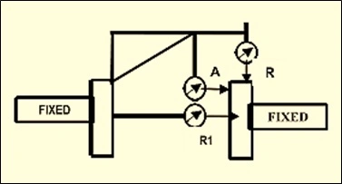
ALIGNMENT TYPES
- Rim (Radial) and Face (Axial) Method
R= radial
A= Axial
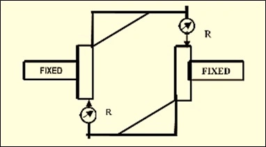
2. Reverse Rim (Dial) Indicator Method
R= radial
ALIGNMENT FIXTURES
- Brackets – should be rigid to minimize sag
- Dial Indicators – shall be calibrated
- Wrenches
✅ GENERAL REQUIREMENTS
- Alignment bracket shall not be used to rotate the equipment.
- Reading shall be at 90 degree increments in the horizontal and vertical plane.
- Readings to be considered valid, the readings and zero shall repeat within 0.02mm (1mil). The algebraic sum of the horizontal readings shall be equal to the algebraic sum of the vertical reading within 0.05mm (2mils).
- Reverse dial (rim) alignment shall be performed while turning both shaft at the same time in the direction of rotation.
- Rim and face alignment is recommended when the coupling hub is greater than the spacing between indicators or one end of the train elements cannot be turn.
- When the shaft cannot be rotated, micrometer measurement wit an accuracy of 0.01mm (0.5mil) are to be used.
✅ FINAL ALIGNMENT TOLERANCES
- All piping is disconnected.
- Fixed and movable shafts free to move.
- Maximum five shims under any support.
- Shim 300 series stainless steel or better material not laminated and flat to 1/1000. At least 3mm (0.125in) but not more than 12mm (0.5in) under movable machine
foot. No more than one ≥3mm (≥0.125in) thick under any foot. - Shim are full bearing.
- Bolts are not undercut.
- Washer are not lock washer and do not yet yield when hold-down bolt are tightened.
- Hold-down bolts are not bolt bound and reasonably centered in bolt holes.
- Soft-foot is not more than 0.05mm (0.002in)
- Pipe Strain checks made in accordance with procedure in Chapter 6-Piping; section 4 par. 1.8.1 through 1.8.5. API 686/REIE 686
✅ API 686 Requirements for Shaft Alignment:
- Machinery and Piping Separation:
API 686 emphasizes the need to separately adjust machinery inlet and outlet piping systems to align with matching machinery flanges. Moving the machinery to achieve piping alignment is strictly prohibited. This requirement ensures that the alignment is accomplished without compromising the position of the machinery.
- Soft Foot Correction:
Before initiating the alignment process, it is crucial to inspect for soft foot conditions. Soft foot refers to gaps or unevenness between the machine feet and the base. According to API 686, no soft foot should exceed 0.05 mm at the hold-down bolt. If a soft foot is detected, corrective actions, such as using shims for adjustment, must be taken.
- Distance Between Shaft Ends (DBSE) Adjustment:
API 686 mandates the verification and adjustment of the Distance Between Shaft Ends (DBSE) based on the manufacturer’s tolerance. This step ensures that the axial or thrust movement of the shaft remains within specified limits. Dial gauges are employed to measure shaft movement, and adjustments are made to center the axial movement for optimal alignment.
- Pre-Alignment and Final Alignment:
Pre-alignment is performed to adjust the vertical and horizontal offset and gap of the coupling. API 686 specifies the use of jacking bolts and shims for achieving alignment. The moveable machinery is adjusted using vertical and horizontal jacking bolts, with shims placed under the feet as required. The alignment of the drive shaft to the machine shaft is verified, and torque requirements for the hold-down bolts are met. Once the initial alignment is approved, the final alignment is carried out after connecting the pipes to the fixed machine.
- Piping Alignment and Pipe Strain Checks:
API 686 necessitates checking the alignment of piping flanges with machinery flanges before tightening the bolts. Measurements are taken to ensure that the pipe flange bolt holes align with the machinery nozzle bolt holes within a specified offset. Pipe strain checks are conducted using laser tooling to measure vertical and horizontal movement as the pipe flange bolts are tightened and can’t deviate more than 0.05mm. Spring supports and/or hanger turnbuckles may be adjusted to align the piping flanges.
- Verification and Reporting:
After the final piping bolt-up, the final shaft alignment is verified. The results of the alignment process, including measurements and adjustments made, are presented in a report to the owner. This report instills confidence in the owner regarding the smooth operation and extended life of bearings, seals, and couplings, minimizing the risk of damage.
✅ Conclusion:
Adhering to the API 686 requirements for shaft alignment in laser alignment processes ensures accurate alignment and reduces the potential for machinery damage. Laser alignment offers numerous advantages, such as enhanced accuracy, real-time readings, and error elimination. By following API 686 guidelines, industries can achieve precise machinery alignment, leading to improved efficiency, reduced downtime, and extended equipment life.
Continue QC Notes Level-25 ⭕ Saudi Aramco Definition of Terms | Important Codes
See More: Aramco Quality Standard
- eBook Welding QC Inspector Interview Questions & Answers Vol-1
- SAMSS Index Download Excel File Free
- Index SAES | Excel | Saudi Aramco Engineering Standards
- Aramco :: Pressure Vessel Reference, Installation Standards
- ARAMCO :: COMPUTER BASED TESTING (CBT)
- PUMP SKID DESIGN
- pump sizing calculator excel
- Centrifugal Pumps and Compressors Installation Standards
- Saudi Aramco form 175 inspection & testing requirement
- HAZOP Vs HAZID in the Oil & Gas Industry
- OIL & GAS PROJECTS CODES & STANDARDS
- Saudi Aramco form 175 inspection & testing requirement
- Saudi aramco form 175 download


![Read more about the article [pdf] List of Aracmo QM Number](https://qcskill.com/wp-content/uploads/2025/04/ARAMCO-QM-NUMBER-LIST-2025-539x360.webp)