
QC Notes Level-27
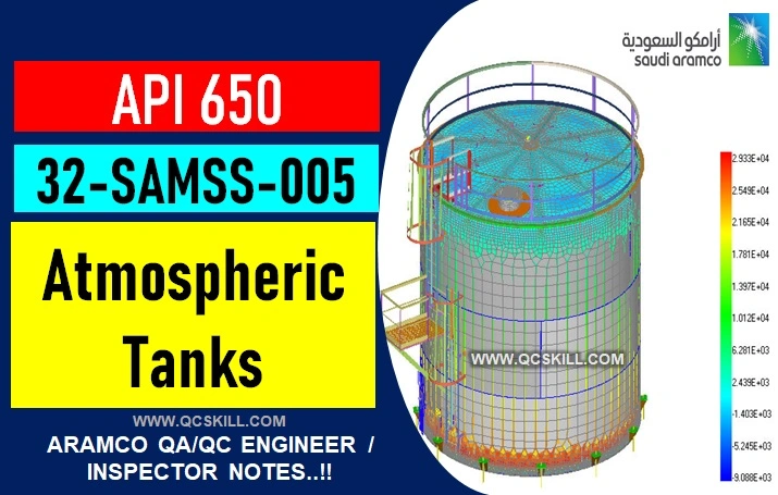
API 650 and 32-SAMSS-005 – MANUFACTURE OF ATMOSPHERIC TANKS
✅ STANDARD REFERENCES:
- SAEP-302 – Instruction for obtaining a waver of a mandatory Saudi Aramco Engineering requirements.
- SAEP-327 – Disposal of waste water from cleaning, flushing and hydrostatic test.
- SAES-A-007 – Hydrostatic testing fluids and lay-up procedure
- SAES-W-017 – Welding requirements for Tanks
✅ DESIGN METAL TEMPERATURE
lowest of the following temperatures:
- Lowest One-day Mean Atmospheric Temperature (LODMAT)
- Minimum Operating temperature
- Hydrostatic Test Temperature
Bolting
- Flange bolting shall conformed to ASTM A193 Grade B7 with ASTM A194 Grade 2H Nuts all coated with fluoropolymer / ceramic coating in accordance with 09-SAMSS-107
- Gaskets shall be non-asbestos according to SAES-L-005 Joints
Joints
- Lap welded joints shall be lap at least 5 times the nominal thickness of the thinner plate joined
- Double welded lap joints shall not exceed 50mm (2 inch)
- Single welded lap joints shall not less than 25mm (1 inch)
✅ FOUNDATION DRIP RING
used to prevent the ingress of rainwater or condensation between thetank bottom and foundation;
- Material shall be carbon steel of 3.2mm thick
- Continuously seal welded to the edge of the tank bottom or annular plate
- Extend at least 75mm (3 inch) beyond the outer periphery of the concrete ring wall
- Top of the drip ring and 75mm (3 inch) height of the tank shall be painted with 250-300 micron (10-12 mils) thick epoxy coating in accordance with SAES-H-001
- Flexible membrane leak barrier (liner) of minimum of 1000 microns (40 mils) thickness compatible with stored products and placed in accordance with SASD AA-36355
- Reinforcing pads and all other external attachment pads shall have rounded corners of minimum 50mm (2 inch) radius and pad that covers the shell shall be provided with 6mm telltale hole.
- Bearing plates shall be twice the diameter of the column section with a minimum of 356mm dia. (14 inch), 12.7mm (1/2 inch) thick and attached to the bottom by 4.8mm (3/16 inch) continuous fillet welds.
- Marking materials shall be free of lead, sulfur, zinc cadmium, mercury, chlorine and other halogens
- Bottom side of the bottom plate shall be cleaned of all foreign matters and grit-blasted cleaned prior to coating, surface preparation shall be according to APCS-3 or APCS-113 10. Weld crown of the annular plate joints shall be ground flush at the contact areas with the first shell course.
✅ SHELL TO BOTTOM WELDS
- Perform oil penetrant leak test on the entire length of the first weld by applying high flash point penetrant oil such as light diesel oil for a minimum of 4 hours (preparably overnight)
- Alternative vacuum test at 35 kPa (5 psi) using a vacuum box fit to the shell to bottom junction
- Inside fillet welds of shell to bottom jont in the cylindrical plate bottom tank shall be examined by either dye-penetrant or wet fluorescent magnetic particle method before hydrotest.
✅ ROOFS
- Roof column support shall be plumb to 1/200
- All material clips, lugs, brackets that are used temporarily for construction purposes shall be removed and ground flush and smooth prior to roof installation.
✅ INSPECTION, TESTING AND REPAIR
- Inspection requirements as per form 175-324900, SAES-W-017
- NDT shall be as per ASME V
- Personnel performing NDT shall be certified as per SAEP-1142 and shall be certified to a minimum level II
- Prior to inspection and final testing the inside and outside of the tank shall be thoroughly cleaned of all slag, scale, dirt, grit, weld spatter, paint and etc.
✅ INSPECTION OF TANK BOTTOM WELDS
- Only vacuum box is permitted
✅ TESTING OF THE SHELL
- Tanks shall be hydrostatically tested by filling it with water of quality in accordance with SAES-A-007
- Hydrostatic testing shall be 24 hours minimum
- Repair of weld shall be as per SAES-W-017
✅ TANK SETTLEMENT MEASUREMENT
- Before hydrostatic tstng has been started
- At the ½ filled point
- At the ¾ filled point
- After 24 hours of filling the tank at the maximum water fill height
- After the tank has been emptied of test water
✅ VACUUM TESTING
- A partial vacuum of 70kPa (10 psi) shall be used for the test
✅ COATING AND PAINTING
- APCS-3 for tank with maximum operating temperature of 70* C (158* F)
- APCS-113 for higher operation temperature
- Tank number and content shall be painted in English and Arabic at 90* around the tanks.
✅ 32- SAMSS-005 Appendix Recommendations
- Top fill layer 100 – 150mm (4-6 inch) shall be a mixture of sweet sand and 3% cement (33:1 ratio)
- Maximum permissible soil content is 0.1% sand shall be dried to a free moisture content of 2% by weight of the dry soil
- Dry sand must be screened through 6.4mm (1/4 inch) mesh maximum
- Sand shall be thoroughly mixed with cement with a ratio of 33:1 by weight in a concrete mixer
- After laying the mixture shall be rolled to a minimum of 6 times by a 3 tons roller
- Vibratory plate tampers maybe used in lieu of the rollers for areas that cannot be reach or cover
- Electrical bonding shunt materials shall be type 304 stainless steel
- Specific gravity shall be 0.7
- Roofs greater than 91mm (300 ft) in diameter shall be double deck type
- Minimum inside width of the ladder shall be 710mm (28 inch)
- Swing type check valve shall be provided at the inlet of the drain
- Siphone type drains are not acceptable for primary roof drain, however it can be used as secondary roof drain if specified in the tank data sheet
- Minimum of two overpressure/vacuum bleeder type vents shall be installed, vent shall be sized to handled 125% of the maximum filling/withdrawal rates
- Bleeder vents shall be designed to open and closed automatically when the roof is 75mm above its low support legs position upon emptying and filling the tank
- Slope shall be 25mm per 3m
- Voids under bottom plates are not allowed
- Three plates lap in bottom shall be 300mm (12 inch) from each other, from the tank shell, from bottom welded annular plate joints, and from joints between annular plates and the bottom
- When annular plates are used they shall be butt welded and shall have a radial width that provides at least 600 mm (24 inch) between the inside of the shell and any lap-welded joints in the remainder of the bottom
- Backing Strip shall be 3mm (1/8 inch) thick tack welded underside of the bottom plate is permitted
- If square grooves are used root opening shall be not less than 6mm (1/4 inch)
- Tank Appurtenance (Nozzle & Manways, venting devices, temperature instruments, level gauging systems, sample connections and stairways/ladders and platforms).
Continue QC Notes Level-28 ⭕
See More: Aramco Quality Standard
What is Aramco – Our Code of Business Conduct.PDF download
- Saudi Aramco Definition of Terms | Code
- eBook Welding QC Inspector Interview Questions & Answers Vol-1
- SAMSS Index Download Excel File Free
- Index SAES | Excel | Saudi Aramco Engineering Standards
- Aramco :: Pressure Vessel Reference, Installation Standards
- ARAMCO :: COMPUTER BASED TESTING (CBT)
- PUMP SKID DESIGN
- pump sizing calculator excel
- Centrifugal Pumps and Compressors Installation Standards
- Saudi Aramco form 175 inspection & testing requirement
- HAZOP Vs HAZID in the Oil & Gas Industry
- OIL & GAS PROJECTS CODES & STANDARDS
- Saudi Aramco form 175 inspection & testing requirement
- Saudi aramco form 175 download


