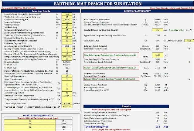
Earthing Mat Design for Sub Station Calculator
The document provides details on designing an earthing grid for a substation based on ANSI/IEEE Std 80-1986 code. It includes input parameters like the area occupied by the grid, soil resistivity, conductor sizes, fault levels, and voltage levels. The design calculations provide the size of the earthing conductor, length of the grid, number of earthing rods, touch and step potentials, and ground resistance to meet safety standards.
Reference: Wikipedia – https://en.wikipedia.org/wiki/Earthing_system
- substation earthing system design calculations
- ieee 80 earthing calculation excel
- earthing system design calculations pdf
- substation earthing pdf
- bs 7430 earthing calculation excel
- earthing calculation formula
Title : Earthing Mat Design for Sub Station
Type : Microsoft Excel Spreadsheet (xlsx)
Size : 50.20 KB
Also search:
Which earthing is best for substation?
Primary requirement of Earthing is to have a low earth resistance. Substation involves many Earthings thro’ individual Electrodes, which will have fairly high resistance. But if these individual electrodes are inter linked inside the soil, it increases the area in contact with soil and creates number of parallel paths.