Piping Inspection & Construction Standards
Aramco QC Notes Level-7
- SAES-L-350 Construction Guidelines
- Cleaning & Erection Procedures
- Pipe Fit-up & Flange Joint Tightening Methods
✅ SAES-L-350 Construction Guidelines
ERECTION AND INSTALLATION (SAES-L-350)
- All sensitive equipment to damage during cleaning and flushing of the piping system SHALL not be installed and SHALL be removed if installed prior to commencing the cleaning process. The list of these equipment SHALL be established during early stages of the execution of the project. Examples of sensitive equipment are: Rotating machinery, orifices, Control valves, Flow element, soft valves, glove valves etc.
- All erected piping system and component SHALL be internally clean and free from foreign
objects.
✅ Cleaning & Erection Procedures
CLEANING
- During project proposal and details design, details procedure for cleaning and flushing of the piping spools and system SHALL be established identifying acceptable method that will be applicable for every individual system category. These procedure SHALL be agreed on by PMT proponent & Inspection Agency.
PRIOR TO INSTALLATION
As a minimum & prior to installation/erection of pipe spools on the Pipe Racks and pipe support the following SHALL be conducted;
- All pipe SHALL be internally cleaned by air blowing. In addition, for large diameters pipes rag cleaning should be conducted if found practically
- All prefabricated pipe spools SHALL be visually inspected for cleanliness, and SHALL have foreign material removed from insaide.
- The pipe ends SHALL be covered after inspection to prevent unauthorized removal of the end cover prior to making the joint to the succeeding section of piping.
DURING ASSEMBLY & ERECTION
- During assembly and erection, the construction agency SHALL ensure that no foreign materials (such as welding consumables, lumbers, gloves, etc.) are lift inside the piping system.
- After assembly and installation, the piping SHALL be cleaned inside to remove all loose material. The cleanliness SHALL be verified visually and/ or by video inspection techniques.
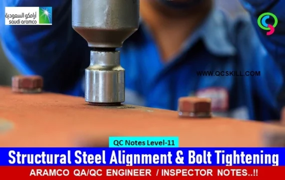
✅ Pipe Fit-up & Flange Joint Tightening Methods
PIPE FIT-UP AND TOLERANCES (SAES-L-350)
- Maximum tolerance for axial dimensions, face to face, center to face and location of attachment shall be ±3mm.
- Flattening of bends measure as the difference between the largest & the smallest outside diameter of any cross section, shall not exceed 5% of the nominal diameter of the pipe.
- Flattening of bends at weld ends shall not exceed 3% of the nominal pipe diameter. Lateral transition of branches and connection from the centerline of the run shall not exceed ±1.5mm.
- Rotation of flanges, measured as the offset between elevation of bolt holes on opposite sides of flange centerline shall not exceed ±2.4mm.
- The tilt of flange measured at the periphery across any diameter shall not exceed 1.6mm from the square position.
- Piping over 3-inch NPS and connected to machinery/equipment, flange alignment shall be within the following limits unless piping analysis per SAES-L-120 shows that loads and moment are within the manufacturers limit for the machinery/equipment nozzles:
a. Vertical bolt hole offset ±2.4mm.
b. Horizontal bolt hole offset ±2.4mm.
c. Rotational offset ±2.4mm.
d. Flange face separation, gasket thickness ±1.6mm.
e. Combination of vertical, horizontal and rotational offset ±3.2mm. - A 6mm weep hole shall be drilled for all dummy support at 6 o’clock position for all horizontal dummy supports.
FLANGE JOINT TIGHTENING METHODS
1) Torque Wrench Method per SAEP-351:
- Torque wrench should be calibrated
- Apply lubricant to stud thread and face of nut contacting the flange
- All stud and nuts installed should be hand tight
- All stud should be number
- Studs are tighten as number with impact wrench or equivalent following bolt tightening sequence 1 st stage tightening @30% of required torque (maximum)
- Required torque value and actual attained value are recorded in
- Bolt Tightening Report
- Final Tightening to ±5% of torque required (actual torque)
- After tightening all bolts have full thread engagement with the nut
- —–Note: complete engagement (less 1 full thread) is acceptable (ASME B31.3 par. 335.2.3)
2) Bolt Tensioning Method (HYDRATIGHT) – 50% Tensioning Method
- Pressure gauge in the Tensioning Machine are calibrated
- Mark bolts in 2 sets, set A and set B
- Tensioners are fitted to every other bolt of set A
- Pressurized the tensioner to pre-determined “pressure A” per approved procedure (this is repeated 2 more times).
- Transfer tensioner to set B bolts and pressurized to pre-determined pressure B and tighten nuts (this should be repeated 2 times).
- —–Note: pressure B is lower in value than pressure A
- After tensioning, Break Loose Pressure is verified to be greater than or equal to pressure B by the following steps Fit the tensioner to one of the tension bolt in set A Pressurized slowly until the nut is loosen using Tommy Bar and socket Once the nut moves, stop pressurizing and record the achieved pressure.
- —–This is the “Break Loose Pressure”(Note:If BLP < pressure B,tensioning isfail)
Continue QC Notes Level-8 ⭕ Saudi Aramco Pressure Testing Standards
See More: Aramco Quality Standard